
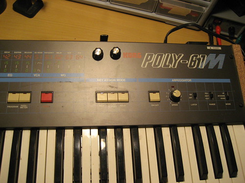
I've been thinking about this for a while, and thanks to some pointers from the Synth DIY mailing list, I've managed to get a nice workable mod for realtime filter cutoff and resonance on my Poly 61.
The digital signal for the filter cutoff can be found coming out IC 42, where a simple DAC is created with 6 signals and some resistors. These lead to IC 36, which buffers the signal and sends it to pin 12 of connector 10A (cpu to voice board).
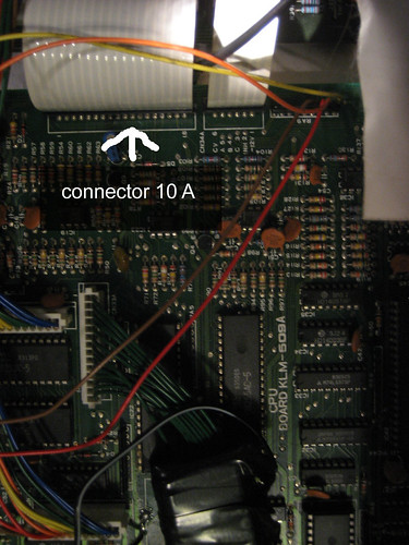
Similarly, filter resonance comes from IC 36, a buffer that is connected to IC 28. Pin 13 is the location on the connector.
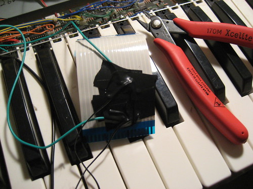
Take the signals from the connector cable by carefully cutting wires 12 and 13 and stripping them. Solder wires and insulate propers (this can be tricky, and messy).
For the cutoff pot, you can create a voltage divider between +5 volts and the signal coming from the CPU board (max cutoff is -5volts). There are many places to get 5 volts, I used Pin 26 on IC28.
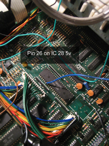
For the resonance, use a ground point for one side of the pot, and the cpu board side for the other, the signal is 0-10 volts.

Probably not the cleanest mod in the world, but simple to do, and it really adds a new level of expression to the cheap and easy to find Korg Poly 61. One note, when you program a patch now, the cutoff level will determine the max cutoff amount the potentiometer will affect, and resonance amount will determine the minimum resonance setting for that potentiometer. In other words, for full range, set the cutoff to 63, and the resonance to 0.
Enjoy non stepped filter sweeps!
25 comments:
Great Job. I understand not everything. What do you mean with CPU board. Where is it located. I see for the resonance 2 black wires going to 12 and 13 from the ribbon and one blue wire, but this one i don't understand were to connect. The two blue (or green ) wires from the ribbon goes to the cutoff. I think that i understand this. but can you please expain me where i have to connect the pins of pots going to CPU ? Thank you in advance. And again , really nice job you did.
Hello here phger again.
If i understand the cutoff i think is like this.
Blue wire goes to PIN26 and the two green to 12 and 13.
I understand the resonance : the two blac wires goes to the same 12 and 13 of the ribbon. And the blue goes to ground ( this i can choose, where did you put it ). You think i understand. Thank You very much.
Last question that will me understand a lot :
Is 12 the CPU side and 13 the rihgt ribbon ?
first thing to note, my battery died on my p61 after I did this mod. I don't think its related, but i need to investigate further.
the cpu board is the one on the left side, connected with the ribbon cable. should actually be labeled, as you can see in the 2nd pic.
the last picture should explain how to wire the pots. the resonance pot: pin 1 goes to the right side of the ribbon cables' pin 13 wire, pin 2 of the pot goes to the cpu side of the ribbon cables pin 13 wire. The 3rd pin on the pot goes to ground (any ground point on the chassis).
for cutoff, you need a wire from pin 1 of the pot going to +5v. I used pin 26 on ic 28...that might be why the battery drained, i still need to investigate. for pin 2 on the pot, use the right side of the ribbons pin 12 wire, and for pin3 use the left, or cpu side.
hope that helps.
Thank a lot for quick respons !
Nice work. I found a similar mod in German, but it was more complicated and I couldn't quite make it all out.
I will try this ASAFP. I have two P-61s(one broken)and have to swap out a midi board which will require a little soldering. Now I have motivation to start and a test machine.
Any findings about the battery drain?
So I finally got this done. It's pretty easy to do. Thanks a lot for sharing. I didn't have a drill handy so I just bored holes in the plastic above joystick. I got the +5 or whatever it was from another source and haven't had a problem with battery drain.
I've been looking at the schematics to see if you could do it with other parameters like PW and ADSR. These are on the same ribbon but I'm not sure how to wire it up yet.
Any ideas? Thanks again.
I finished this mod without difficulty. Instead of cutting and soldering into the ribbon cable, I soldered j-plugs onto the bottom of the boards under the female connectors. I used a male/female pair, to make it easier to undo the mod. This way, the j-plugs can just be joined instead of taking the boards out.
I took the power and ground from the arp board attached to the cover. The solder points are clearly labeled "+5" and "ground," so some tinned leads got attached there. This way it reduces the risk of frying an unobtainable chip.
My only concern: there is still some "steppiness" to the filter sweeps. It could be the value of the pots that I used. I had B500k available - what else has been used by y'all and what were the results?
I cant believe that no one posted the value of the pot for this mod. If anyone is still interested it is 100K linear
If anyone still looks here and is interested, I have the circuit for part of the left hand panel mod. It enables you to switch between the joystick and 2 pots to control the vcf and dco together or independently
I'd like to see the schematic or pics for the mod if available, please!
I cant post pics, I could email you it, or if you know how to put pics in the forum then I will put it here
To post a pic, open up the "compose" page and look for the little box that looks like a polaroid next to the word "link." It is slightly off center to the right. That will let you post a pic.
Thanks a lot!
JTR
Nice mod, I am in the process of doing this to mine, but am getting confused about what side of the ribbon to connect for each pot? Please could you email me the details for both pots and where all 6 wires connect? Please let me know before I see smoke coming from my synth. Many thanks- brodymagdalene@gmail.com
Hey Brody, I have carried out the mod described in this blog and made a video on youtube you can check out.
Might help show you the mod in action and where I have the cables connected.
https://www.youtube.com/watch?v=AN4dt3e46Is
Its been quite a while since I did this mod and I don't have the synth anymore but I found it by just poking around the connections at the ribbon connector. Looks like retrop has it nicely sorted! Good luck!
I think I may have idea why my pots aren't working propperty! I soldered my wires to the under side of the boards and left the ribbon cable intact! I and now thinking that the ribbon cable pins 12 & 13 should have my pots in between the connections and not aswell as. Hopefully this will sort it. I will try tomorrow and write up what happens just incase it helps somebody in the future.
Success! That fixed was the problem, I took the ribbon cable out and put sellotape over the 2 pins (12&13) pluged it back it and it works like a charm. Thanks for the help fellow synthers.
I still have the circuit for the left panel mod to switch between joystick and pots to control the up down functions independantly, but cant seem to post pics just words :>(
Hi spikey, thanks bro, that would be cool to have! Could you email me a zip file with the pics and the how to info please, I couldn't figure out how to put pics on here either. brodymagdalene@gmail.com
Post a Comment